Sensor Types and Selection
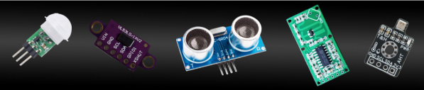
🖺 Additional Sensor Information:
The companion written guide has more details on sensors, including wiring diagrams, parts and scenarios for use. This section just provides an overview of these options, primarily as it relates to the firmware configuration.
As covered in the preceding section, the system can use up to two wired sensors connected directly to the primary controller. The controller also offers support for two (or more) wireless sensors. Of course, either type has its own pros and cons.
🔌 Wired Sensors (Direct Connection)
Wired sensors connect directly to the GPIO pins of the primary ESP32 controller. The firmware natively supports up to two wired inputs utilizing either AM312 PIR motion sensors or VL53L0X Time-of-Flight (ToF) distance sensors.
👍 Advantages
- Only one ESP32 is needed: A single controller runs the entire system
- Instantaneous Response: Zero network latency. Because the trigger signal travels directly over copper to the processor, the light activation is immediate.
- Network Independence: Fully functional even if your local Wi-Fi router crashes or drops offline. The local hardware loop handles everything.
- Simplified Power Infrastructure: The sensors draw their power directly from the primary controller’s 3.3V rail. There is no need to deploy independent power supplies or batteries at the sensor locations.
⚠️ Limitations
- Physical Installation Friction: Requires physically fishing cables through walls or under steps from the top/bottom of the staircase or from one end of a hallway all the way back to the main controller enclosure.
- Signal Interference Risks: Long cable runs can act like antennas, making them susceptible to electromagnetic interference (EMI) from nearby AC lines or high-current LED lines, which can require hardware filtering (resistors/capacitors) to prevent ghost triggers.
- Sensor Types Must Match: When using two sensors, both must be of the same type… either PIR or ToF. You cannot mix different types.
Using Custom Wired Sensors
The firmware is designed to support either a standard PIR sensor (AM312 tested) or a VL53L0X distance sensor “out of the box”. You can theoretically use a different sensor if that sensor simply sends a 3.3V HIGH signal when triggered and a LOW signal when clear to a single GPIO pin. Configure this sensor as PIR in the settings as the firmware simply listens for HIGH/LOW on the designated GPIO pin.
For other sensor types or those that require more than one GPIO pin (like I2C devices), then a firmware modification will be necessary, possibly with additional libraries to support the type of sensor in use.
🛠️ A Gentle Reminder
While repeating myself, it is important to understand that I simply don’t have the bandwidth to maintain multiple versions of the firmware for different sensor options. If you desire different sensors, different ESP versions, etc. you will be swimming on your own! While I’m happy to answer questions, I can only officially support the firmware as designed.
📡 Wireless Sensors (Network Integration)
Wireless sensors act as independent edge devices on your local network. The project provides custom companion firmware for a secondary ESP32 module configured with an AM312 or VL53L0X sensor.
👍 Advantages
- Effortless Deployment: No need to run communication wires through your walls or stair stringers. You only need local power at the sensor’s mounting point.
- Uncapped Scalability: While wired setups are constrained by physical GPIO pin limits, the firmware’s local web server can accept incoming data strings from multiple wireless endpoints or zones.
- Ultimate Hardware Flexibility: You are not locked into my hardware or firmware. As long as your custom sensor platform can send a local HTTP API GET request or publish to an MQTT broker, you can integrate any third-party device or firmware into the project.
- Sensor Types Can Be Different: Unlike the wired option, you can mix/match different wireless sensor types. This can allow better zone detection by mixing longer range/wider POV sensors with shorter, narrow POV sensors.
⚠️ Limitations
- Network Reliability Dependency: If your local Wi-Fi network experiences high traffic, congestion, or drops offline, the sensors will be unable to communicate with the primary controller.
- Power Drop Requirements: Each wireless sensor station requires its own independent power source (such as a 5V micro-USB adapter) and its own microcontroller to handle the network stack.
- Minor Network Overhead: Introduces a tiny fraction of a second of latency as the data packet travels through your wireless router compared to a direct-wired connection.
Using Custom Wireless Sensors
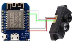
If you opt to use the included firmware for your wireless PIR or ToF sensor, you only have to tell the system whether to consider the sensor as Sensor1 or Sensor2. The firmware handles everything else, including reporting its state changes to the primary controller.
But you are not limited to using the provided firmware that only supports a PIR or ToF sensor. You can pretty much build any type of sensor you like, using any hardware and firmware, as long as the firmware can meet any ONE of the following requirements:
- Send a local API call: This means the controller’s firmware can send an ON or OFF HTTP message to the primary controller’s IP address. Speficially, this is handled via an HTTP GET request using the folloing ULR structure:
http://primary_ip_address/api?devicenum=2&state=on
OR
- Post an MQTT Message: If you have a local MQTT broker (or even the Home Assistant MQTT add-on/app), the custom wireless controller can simply post state changes to MQTT and the primary controller will listen for the messages to control the LEDs. In addition to an MQTT broker, you must configure the primary controller for MQTT. This is covered
OR
- Is Integrated in Home Assistant: If you are a Home Assistant user, you can use Home Assistant automations to either send the local API call or post an MQTT message (if you also have MQTT). This means you can pretty much use any sensor or other entity as a trigger to control the LEDs. However, you may instead wish to integrate the primary controller into Home Assistant. This can be done via a single button click in the primary controller’s app. See the section on Home Assistant Discovery for more details on this option.
With these options, if you prefer not to use the provide wireless sensors and firmware, you can custom build a sensor that triggers the LEDs based on pretty much anything… temperature, light level, door or window sensor, etc. As long as the sensor/controller can either send an HTTP API call or post an MQTT message, you can use it as a wireless sensor with the system.
Use of the HTTP API and MQTT are covered in more detail in a later section of this guide.
Using more than Two Wireless Controllers
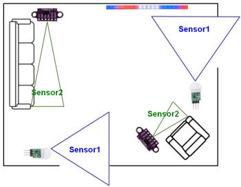
When using wirless controllers, it is possible to use more than two sensors. Theoretically there isn’t a maximum, but each sensor will report as “Sensor1” or “Sensor2” to the primary controller. If more than one sensor is configured as “Sensor1” then when any of those sensors trigger, the primary controller will treat it as “Sensor1”. This is somewhat similar to having multiple triggers in a Home Assistant automation. The automation will run if any of the triggers fire. The written companion guide has more information on using multiple sensors, including a couple of sample scenarios where this might be implemented.