The Boot Process

This section ONLY applies to the Primary Controller.
A lot is going on in the background when a controller first boots up… connecting to WiFi, configuring the hardware, staring up the web server and API routines and connecting to an MQTT broker (if enabled). The LEDs can be used to provide some basic indicators of this boot process and can help you determine where a problem may exist of the controller isn’t functioning as intended.
Visual Boot Indicators
When you power on the primary controller, the following steps occur:
- The system looks for configuration file in its own storage (SPIFFS) partition. If not found, it enters ‘Onboarding mode’ and starts the WiFi Hotspot. Setup halts at this point.
- The system attempts to connect to WiFi. Again, if it fails, it enters Onboarding mode and further setup halts.
- The configuration file is opened and your particular system settings are loaded.
- Sensor hardware, if wired sensors are used, are configured and initialized.
- The LEDs are then tested.
This is where the first visual indicator is shown. If the above steps all complete successfully, the LEDs will briefly flash solid red, green and then blue.
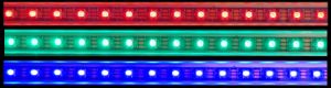
If this doesn’t occur within a minute or so of powering on the controller, then one of the above steps has failed. Try looking for the WiFi hotspot. If this is broadcasting, then the issue was either with the configuration file or with joining WiFi.
🛠️ Please Note
The default configuration used upon initial power up after onboarding defaults to GPIO4 for the LED data and has an LED count of only 30. If your LED strip has more LEDs than this, only the first 30 will light up for this test. If you used a different GPIO pin, the LEDs won’t light up at all. It doesn’t mean anything is wrong with your system. You will just need to use the web app to specify the actual number of LEDs and/or the GPIO pin used. Future tests will then light up the entire strip.
If the initial configuration passes, the boot process then continues:
- A connection to the MQTT broker is established (if MQTT has been enabled and configured)
- The Arduino OTA function is configured and enabled. For this test, another visual indicator is shown on the LEDs.

The Arduino OTA function is used to compile and upload the source firmware to the controller wirelessly from the Arduino IDE, such as when you are modifying the source code and installing your own firmware version. There is a separate and different from the normal firmware upgrade process. When activated (via the web app), the LEDs will turn a solid alternating red and green color. This means the system is ready to accept a new firmware file over-the-air from the Arduino IDE. During the boot process, this doesn’t mean the system is ready to accept an upload, only that the Arduion OTA function is active and available. The red-green LEDs will only be lit for a few seconds to indicate this available functionality.
⛔ Disabling LED Test
There is an option to disable the LED test in the web application. This will prevent the LEDs from flashing red, green and blue during the boot process. However, the Arduino OTA indication will still be briefly displayed. It is recommended to leave the LED test enabled.
Once all boot steps have completed, the LEDs will turn off and the system is then ready for normal operation.
Technical Details (For Advanced Users)
If you are modifying the firmware or troubleshooting a communication issue, understanding the “Under the Hood” sequence is vital.
Configuration Files
Both the Primary and any Wirless Display controllers each have their own local configuration files for Wi-Fi credentials. Any changes to the settings are also saved in a JSON file, located in the SPIFFS/LittlFS partition on the ESP32. This is the file that where any configuration changes made through the web inteface are stored. This is read during the boot process to setup the system with your desired parameters.
If something isn’t behaving as expected, looking at the contents of the configuration file is always a good place to start. If you can access the controller’s web application, there is a ‘config dump’ feature that will read and display the contents of the config file.
If you cannot reach the web interface due to a boot up issue, you can also connect the controller back to a computer via USB and use the previously covered ESPConnect to view the contents of the config.json file.
Multiple Controller Boot Sequence
When using wireless sensors with their own controller, each has its own boot process and configuration file. One parameter used by wirless controllers is the IP address of the primary controller (for sending state updates via the API). As part of the boot process, the wireless controller attempts to ‘ping’ the primary controller at the specified address. If not successful, the wireless controller more or less goes into standby mode and won’t detect any sensor changes. If this happens, you can simply restart the wireless sensor or you can open up the wireless controller’s web page and use the provided “Test/Ping” button. This will attempt to reach the primary controller again and reestablish the connection. Once completed, the wireless sensor will return to normal operation.
The wireless controllers have no good way to show the boot process, but there is a small trick that you can use to let you know if the wireless controller is sending data. This is done using the ESP32’s onboard LED. You can read more about that option in the following section on Setting up the System.
With the boot process understood and your initial onboarding verified, you are ready to complete the initial setup via the web application to make the system actually work!