Onboarding and First Time Setup
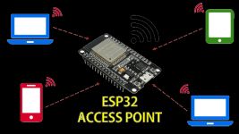
Once you have successfully flashed the firmware to your Primary and Display controllers, the next step is to connect them to your local Wi-Fi network.
🌐 Local Network Reminder
While these devices require a Wi-Fi connection to provide the web interfaces or to communicate with each other when using wireless sensors, they do not require any Internet access for full functionality.
1. Primary and/or Wireless Sensor Controllers
You must perform this process once for the primary controller and then again for each wireless sensor you plan to use.
⚠️ Mutiple Sensor Notice
As covered in the previous section, if you planning on using more than one wireless sensor, you should flash and complete these onboarding steps BEFORE flashing the firmware for the next wireless sensor. This avoids multiple devices attempting to broadcast the same hotspot simultaneously.
Step 1: Join the Hotspot
Once flashed, the controller will broadcast its own Wi-Fi network. It’s essentially a very tiny, very exclusive club where the only item on the menu is “Configuration.” If your phone warns you that the “Network has no Internet access,” take a deep breath and tell it everything is fine. We aren’t here to browse cat memes; we’re here to give a the controller its identity.
The default hotspot names for the Wi-Fi hotspots are:
- Primary Controller:
STAIR_LEDS_AP - Wireless Sensor Controller(s):
WIRELESS_SENSOR_AP
As noted earlier, these hotspot names may show your assigned DeviceName_AP instead of the above.
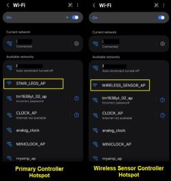
Use a phone, tablet, or laptop to join the hotspot. Remember, if your device warns you that there is “No Internet Connection,” select Stay Connected.
Step 2: Access the Onboarding Form
Open a web browser and enter the IP address: 192.168.4.1. The onboarding form will appear:
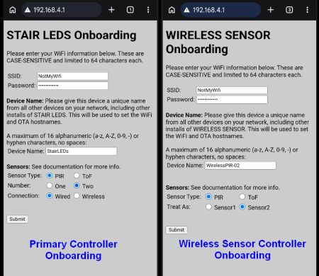
Fill out the following common fields for both controller types:
- SSID: Your Wi-Fi network name (must be the same for all devices/controllers used).
- Password: Your Wi-Fi password.
- Device Name: A unique, short name (up to 16 alphnumeric characters plus the hyphen [-], no spaces).
- Example:
led-control01andToF-Wireless01. - Each controller on your network must have a unique name.
- The device name is not only used to help you identify which controller is being accessed via the web application, but this also used for the WiFi connection and as the MQTT client if MQTT is enabled. Therefore, all devices (regardless if a primary or wireless controller) should have a unique name across all other devices on your local network.
- Example:
Then complete the sensor fields accordingly. These are similar but slightly different depending on whether you are onboarding a primary controller or a wireless sensor controller.
Sensor Fields These fields just provide the initial sensor configuration settings. They can be changed via the web application after onboarding.
Primary Controller
- Sensor Type: Only applies if using wired sensors. Indicates whether PIR or ToF sensors are used. Ignored if wireless sensors are selected.
- Number: Tells the controller to listen for one or two sensors. Applies to both wired and wireless sensors.
- Connection: Tells the system whether to use its own local wired sensors or to listen for updates from wireless sensors. When ‘Wireless’ is selected, the Sensor Type setting is ignored.
Wireless Sensor Controller
- Sensor Type: Tells the local firmware whether a PIR or ToF/Distance sensor is used.
- Treat As: Indicates whether this wireless sensor should report as “Sensor1” or “Sensor2” to the primary controller.
If you wish to use a different sensor type and/or more than two sensors, this is possible with a couple of caveats. See the section on Sensor Selection for more information.
Step 3: Submit and Verify
Once you have completed all fields, click Submit. The controller will reboot and attempt to join your network. The onboarding page on your mobile device will show the connection status.
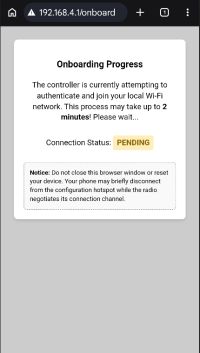
Depending your WiFi strength, it may take up to two minutes for the connection to be established. Do not navigate away from the status page or change the Wifi connection on your mobile device during this process.
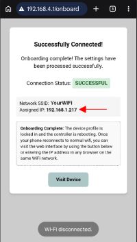
Once the controller successfully joins your WiFi, the status page will update to a ‘Success’ message and the page will show your SSID and more importantly the newly assigned IP address for the controller. This is the IP address you will use to access the firmware’s web application and settings.
The controller will then stop broadcasting the hotpsot and your phone or mobile device will disconnect and should reconnect to your normal WiFi. Once this step is complete, you can even use the ‘Visit Device’ button to immediately go to the controller’s web interface.
But if the controller is unable to connect to your WiFi for any reason, the following status page will be shown instead:
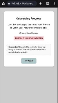
If you see the above status page instead of the ‘Success’ page, it means the controller was unable to connect to your WiFi using the provided information. This could be an improperly entered SSID or password (these are CASE-SENSITIVE), a firewall issue or other network-related problem. When this occurs, the hotspot will start broadcasting again. If you are still on the hotspot WiFi, you can simply click ‘Try Again’ to return to the onboarding page. If your phone disconnected from the original hotspot, you’ll need to reconnect before returning to the main 192.168.4.1 onboarding page.
If you run into any issues with the onboarding process, see the Troubleshooting section for common issues and resolutions.
3. Assign Static or Reserved IP Addresses
This step is strongly recommended when using wireless sensors.
Any wireless controllers communicate with the primary controller using an IP address. If your router reassigns a new IP to the primary controller (due to a power failure or lease expiration), the system will stop functioning as the wireless sensors will be sending their state to the wrong IP address. In addition, any IP changes means that the IP address used to access the controller’s web interface will also change.
When using wireless sensors, it is highly advisable to assign a static or reserved IP address for the primary controller. Assigning reserved IP addresses to wireless sensor controllers is options, but worth consideration so that the IP address for the web interface always remains the same.
- Open your router’s configuration page.
- Create a Static Reservation for the Bulb, Primary Controller, and Display Controller.
- Power cycle each device to ensure they are using the newly assigned static IPs.
4. Final Hardware Integration
At this point, you should move your controllers from your computer to their final positions (either on a breadboard or to their permanent soldered board).
Build Resources
If you haven’t completed the physical build yet, refer to these guides:
⚠️ Additional Setup Required
Don’t expect the system to function as expected immediately after onboarding. Initially, the system will use a number of default startup settings. This includes things like the number of LEDs, power settings, remote controller IP address (for wireless sensors) and so on. You will need to complete some additional hardware settings via the controller’s web interface and save these changes to the local configuration for each controller after it is onboarded for full functionality.
Once your hardware is connected and powered, you can jump to the Hardware Configuration section to finish the controller setup.