Hardware Configuration - Wireless Controller
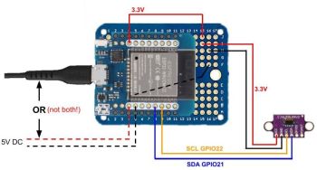
If you opt to build and use wirless sensors, each sensor has its own dedicated controller and therefore its own configuration and embedded web applicaation. For the primary controller, you simply need to set the sensor type to ‘wireless’ (see prior topic). All other configuration is handled via the wireless controller’s app.
🛠️ Using Multiple Wirless Sensors
If using multiple wireless sensors, you must configure each sensor indendently using its own local web application and configuration file. Use distinct and meaninful device names when onboarding the controller so you can easily identify which sensor is which.
Even if you are using Wireless sensors for your system, you may wish to review the previous topic on wired sensors since a lot of the information provides, such as a restriction on GPIO 0, apply to all sensor types whether wired or wireless.
Accessing the Wireless Controller’s Setings
Similar to the primary controller, you access the web interface page by entering the controller’s IP address in a browser of any device on the same network.
<img src="images/wireless_main_full.jpg" alt="Wirless Main"
Unlike the primary controller, the hardware settings are right on the main page. In fact, this is the only setup/settings page for the wirless controller. Many settings for the sensors are similar to those settings for wired sensors, but with some distinct (and important) differences.
System Settings
There is only one system setting
LED Controller IP Address</b>
Wirless controllers communicate and send their state changes to the primary (LED) controller via WiFi. To find the primary controller, the IP address is used. For this reason, you should onboard and configure the primary controller before setting up any wireless sensors.
⚠️ Static or Reserved IPs Recommended
If the primary controller obtains a new IP address from your router/DHCP server due to a restart, lease expiration, etc., then the system will break as the wireless sensors will no longer be able to find the primary server and will need to be reconfigured for the new primary’s IP address. For this reason, it is strongly recommended that you assign a static or reserved IP address to at least the primary controller.
Test / Ping Button: You can use this button to test the communication between the wireless sensor and the primary controller. Results will show one of the following:
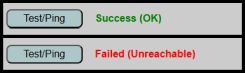
If you receive the failure message, verify the IP address of the primary (LED) controller and that it hasn’t been assigned a new IP address. If you still not get the wireless sensor to communicate despite using the correct IP address, see the Troubleshooting topic.
Sensor Settings
Recall that these settings are configured independently for each wireless sensor, so each sensor can have its own unique settings, irregardless of other wireless sensors.
Sensor Type Select whether this sensor is using a PIR or ToF sensor. Unlike wired sensors, where both sensor have be of the same type, you can mix/match sensor types when using more than one wireless sensor. Like the primary controller, the options available will change based on the type of sensor selected.
Treat As
Indicate whether the sensor should report as “Sensor1” or “Sensor2” to the primary controller. Note that when using wirelesss sensors, it is possible to use more than two sensors. But each sensor must be reported as “Sensor1” or “Sensor2”. This means that you can have multiple sensors report as a single sensor back to the primary controller. See the section on Sensor Type and Selection or the separate Build Guide for more details on using more than two sensors.
If the primary controller is configured to use TWO sensors, then you must have at least two wireless sensors, one reporting as “Sensor1” and one as “Sensor2”. If using multiple sensors but want them all treated as the same by the primary controller, set the primary sensor to only use one sensor and define all your wireless sensors as “Sensor1”.
⚠️ Note:
You cannot have the primary controller set to one sensor and then define all your wireless sensors as ‘Sensor2’. Sensor1 must exist before adding additional sensors as Sensor2.
Use Onboard LED
Since there is no display or other method to indicate the state of a wirless sensor, we can take advantage of a controllable LED on the ESP32 board itself.
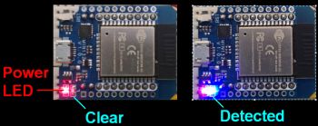
Most ESP32 boards have a power LED (generally red) that is illuminated whenever the ESP32 has power. But most also include a secondary LED (generally blue) that is controllable via a GPIO pin. When the option to Use Onboard LED is enabled, then whenever the controller detects a trigger from the sensor and sends that state to the primary controller, the blue LED will illuminate. As soon as the sensor ‘clears’ the LED will turn back off.
This process also listens for a reply from the primary controller. If the primary controller is not reachable or isn’t responding, then the blue LED will not illuminate because the signal was never received. In addition, if the primary controller is restarted, you’ll see the blue LED on all sensors briefly illuminate when a connection from the primary server is reestablished.
This can be extremely helpful when building and setting up your system. It not only lets you know that a sensor is firing as expected, but that the state is also being sent to, and received by, the primary controller. For PIR sensors, it can also help determine the native cooldown period as the LED will remain illuminated until the sensor resets to a “clear” state. Once your system is configured and operating properly, you can toggle this option back off if you don’t want the local LED to light up each time the sensor is triggered.
LED GPIO Pin
As mentioned, most ESP32 development boards use GPIO2 for the onboard LED. If your board uses a different GPIO, simply specify it here. If your board doesn’t have a controllable LED, then just disable the Use Onboard LED option. When disabled, the GPIO pin is simply ignored and no trigger signal will be sent for an onboard LED.
PIR Sensors
If you select PIR as the sensor type, then there is only one other setting available.
Data GPIO Pin</u>
Simply indicate the GPIO pin where the data line from the PIR sensor is selected. GPIO18 is provided as a default, but you can use any appropriate digital GPIO pin.
ToF (VL53L0X) Sensors
If you select ToF as the sensor type, then the PIR field is replaced by fields specfic to a ToF sensor.
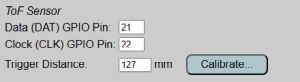
GPIO Pins
VL53L0X (ToF) sensors are I2C devices and therefore have two GPIO pins… one for data and one for clock. Simple enter the GPIO pins you used for your sensor(s). Recall that GPIO0 cannot be used.
Trigger Distance
ToF sensors use distance instead of motion. This can be an advantage in certain situations (see the earlier Sensor Type and Selection topic and the related Build Guide for more details). The ToF sensor will trigger (send a “DETECTED/ON” state) any time an object appears within the sensor’s view and within the specfied distance. If an object is detected, but is outside of the specified distance, the system will not trigger a detected message. Once the object clears the field of view or moves outside the specified distance, the sensor will send a “CLEAR/OFF” signal to the primary controller. Distances are always entered in millimeters (mm).
Due to the specs of the VL53L0X, the maximum distance value is limited to 1200 mm. Minimum distance should be greater then 30mm, but the minimum isn’t enforced on the settings page. Note that accuracy may suffer at the lower and upper end of this range (<30mm or >1100 mm).
Also note the “Calibrate” button that appears only for ToF sensors. Calibration of ToF sensors are covered under the General System Use topic.
Saving and Committing Your Changes
If you make any changes on the Hardware Setup page, you must click the “Save & Reboot” button to commit your changes. The system will update and save your local configuration file. The controller then reboots and loads your new values from the configuration file. Once the reboot completes, the sensor will reestablish the connection to the primary controller.
If you make changes, but want to revert all settings back to the previous saved values, simply click the “Reset” button to read the setttings from the saved configuration file. Those values are then reloaded on the page.