Hardware Configuration - Primary Controller
After onboarding is complete and you are able to access the firmware’s integrated web app, there are some initial hardware settings that need to be configured before the system will be fully operational. These settings are slightly different depending upon whether you are working with a primary or wireless sensor controller.
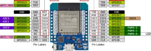
👉 GPIO Pins
The system allows you to use different GPIO pins for your devices other than the defaults provided with the firmware. But note that your cannot use GPIO 0 for any of your settings. While GPIO 0 is a valid GPIO pin on most ESP32s, within the context of this application, using “0” as a GPIO pin means that device is not used. Do not set any GPIO pins to “0” unless you truly are not using that device/connection.
The primary controller is the one connected to the LEDs and if you are using wired controllers, it will be the only controller. Begin by opening the integrated web app by just going to the IP address of the controller in a web browser of any machine on the same network.
On the main page of the web application, look about midway down the page for the Hardware Settings button:
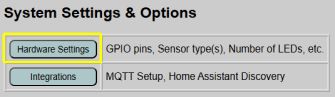
We’ll come back to the other options on the main page in a bit, but we must configure the hardware first.
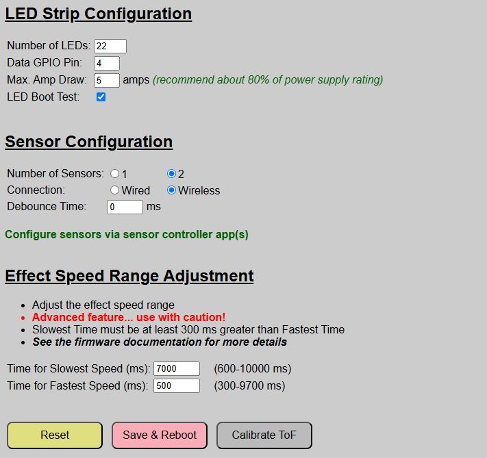
On this page, you configure your LEDs and the sensors used. You can also optionally adjust the speed range for effect speeds.
LED Strip Configuration
Number of LEDS
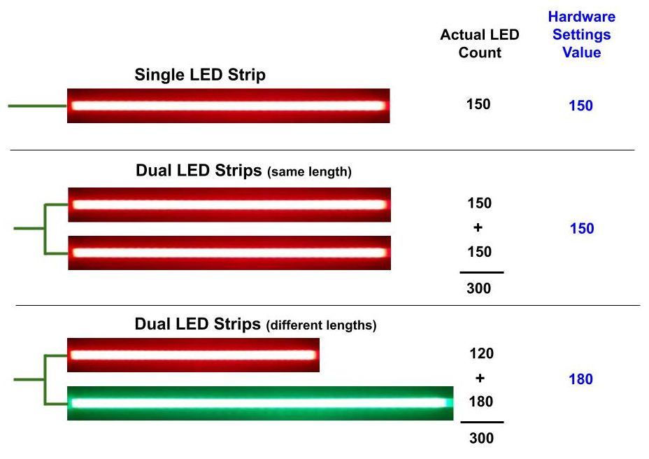
The system needs to know how many LEDs are in use. Note that the system is sending out a single data signal, so if you are splitting the data signal between two identical strips, you should only enter in the number of LEDs in ONE strip. If your two (or more) strips have an unequal number of LEDs, use the number of the strip with the maximum number of LEDs.
Data GPIO Pin
The system defaults to GPIO4 for the LED data line. If you used a different GPIO pin, simply specify it here. Note that the LEDs will not light at all (even during the boot process) until the proper GPIO pin has been specfied and saved.
Max Amp Draw This is a safety setting that will limit the LED brightness in an attempt to limit the curernt (or amp) draw from the power supply. LEDs can pull substantial current (each LED RGB “pixel” can draw up to 60 mA for full bright white). For example, trying to run 200 LEDs (5V WS2812b) at 100% bright white can theoretically pull up to 12 amps!
⚠️ IMPORTANT
When determining the appropriate power size and max amp rating, and unlike the Number of LEDs above, this should be determined based on the total number of LEDs in use and not just a single strip if using more than one.
It is recommended to set this value to approximately 80% of the max peak amp rating of your power supply. For example, if using a 10A power supply, set this value to 6A.
LED Boot Test
This indicates whether the LEDs will be used during the boot process to show certain steps. If unchecked, then the LEDs will not be used. See The Boot Process topic for more details. Note that the Arduino IDE initialization will be shown on the LEDs regardless of this setting.
Wired Sensor Configuration
This tells the controller the number, type and connection method that your sensors will use.
Note that what is shown on the page will dynamically change as you make selections, but the biggest difference is the result of selecting wired or wireless sensors. This section primary covers wired sensors. Setup and configuration for wireless sensors are covered in the next section.
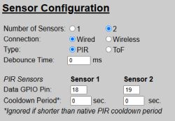
Number of Sensors
Wired sensors are connected directly to the primary controller. Indicate whether you have one or two wired sensors attached. If you select “1”, then the fields for Sensor2 are hidden or disabled.
Connection
Select ‘Wired’ for sensor(s) directly connected primary controller. See the next section if using wireless sensor controllers.
Type
Indicate whether your sensors are using PIR or ToF (VL53L0X). Note that for wired sensors, all sensors must be of the same type. If you need to mix/match sensor types, consider using wireless sensors instead. The type selection will determine the remaining fields shown.
Debounce Time
Only increase this setting if you are getting “ghost” triggers. You can ‘debounce’ the signal to ignore short triggers that only last a few milliseconds. However, the larger this number, the larger the delay between a real trigger and an LED response. Start with “0” and only increase by 10 or 20 milliseconds at a time until the ghost triggers cease.
PIR Sensors
When PIR sensors are selected, then the fields shown in the above image will be displayed.
Data GPIO Pin
Specify the single GPIO pin that your PIR sensor uses for the data line. If you use a pin other than the default, be aware that GPIO0 cannot be used per the note above.
Cooldown Period
PIR sensors, by their nature, have a standard or default ‘cooldown’ period. This cooldown period is the amount of time the sensor continues to show motion as “detected” even after motion has stopped before it resets to a “clear” state. For some PIR sensors, this might only be a couple of seconds. For others, it can be 30 seconds or more! If you have a particular need, you can increase this cooldown period, but you cannot make it shorter than the native cooldown of the PIR sensor itself.
Why might you want to increase the cooldown period?
The system has a default LED On Time (covered under Using the System). Unless triggered by some other event, the LEDs will remain on for this amount of time before automatically turning off. This countdown only starts when all sensor(s) report “clear”. If a sensor triggers again during this countdown period, the countdown restarts. If you have a PIR sensor with a short cooldown (say 2 seconds), but in your case, you want to wait for 30 seconds to assure no additional motion/triggers occur before starting the countdown, you can specify a 30 second ‘cooldown’ for the sensor. In this case, the countdown won’t begin until the sensor has reported “clear” for at least 30 seconds. This is a niche case, so unless you have a need, leave the cooldown period at zero and the native cooldown of the sensor will be used. Note this value is entered in seconds, not milliseconds.
ToF (VL53L0X) Sensors
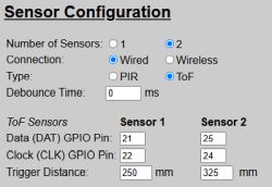
When selecting the ToF sensor type, some of the data fields change.
Debounce Time
This is basically identical to the PIR setting (see above). This difference is that it will ignore brief triggers of distances less then the trigger distance, which is covered below. But the same rules apply. Leave this setting at “0” unless you are getting ghost triggers and only increase by 10 or 20 milliseconds at a time until the ghost triggers stop.
GPIO Pins
VL53L0X (ToF) sensors are I2C devices and therefore have two GPIO pins… one for data and one for clock. Simple enter the GPIO pins you used for your sensor(s). Recall that GPIO0 cannot be used.
Trigger Distance
ToF sensors use distance instead of motion. This can be an advantage in certain situations (see the earlier Sensor Type and Selection topic and the related Build Guide for more details). The ToF sensor will trigger (send a “DETECTED/ON” state) any time an object appears within the sensor’s view and within the specfied distance. If an object is detected, but is outside of the specified distance, the system will not trigger a detected message. Once the object clears the field of view or moves outside the specified distance, the sensor will send a “CLEAR/OFF” signal to the primary controller. Distances are always entered in millimeters (mm).
Due to the specs of the VL53L0X, the maximum distance value is limited to 1200 mm. Minimum distance should be greater then 30mm, but the minimum isn’t enforced on the settings page. Note that accuracy may suffer at the lower and upper end of this range (<30mm or >1100 mm).
Wireless Sensors
If you select wireless sensors on the hardware setup page, then other than debounce time (which will be applied to any signals received from the wireless sensor in the same manner as wired), all other settings are hidden.
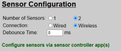
As shown, wirless sensors are configured via their own controller app. This is covered in the next topic.
Effect Speed Range Adjustments
For most effects, you can specify a speed using a scale from 1 - 10 via a slider control on the main page. This speed scale corresponds to how long it takes to complete the “drawing” or rendering of an effect on the LED strip(s).
Note: Not all effects use the speed setting. For example, the “Solid” effect does not use speed.
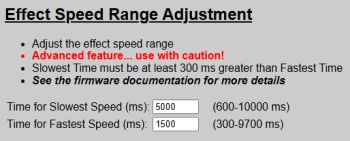
❗ Warning
This is considered an “advanced” setting. Improper use could make your system unstable or even crash the controller. Be sure you understand these settings before adjustment. More detailed information can be found in the Advanced topic on Effects and Speed.
Time for Slowest Speed 
This indicates approximately how long (in milliseconds) an effect will take to complete with a speed scale setting of 1. The valid range is 600 ms to 10000 ms (0.6 - 10 seconds) for the slowest setting.
Time for Fastest Speed 
This indicates approximately how long (in milliseconds) an effect will take to complete with a speed scale setting of 10. The valid range is 300 ms - 9700 ms (0.3 - 9.7 seconds) for the fastest setting. The fastest setting must be at least 300 ms less than the slowest setting.
Why Adjust the Speed Range?
The system uses the speed settings to determine how long it takes to render or draw an effect on the LED strip(s). But this is a ‘relative’ speed that is also depending on how many LEDs your have or how long the LED strips are.
For example, say you have an effect speed that attempts to draw an effect, such as Chase which lights up each pixel in sequence, in a one second period. If you run this same effect/speed on an LED strip with 200 LEDs, it will appear to have a relative speed that is twice as fast as a strip with 100 LEDs. While the default settings may work fine for most projects, if you have an install with a low or high number of LEDs, you may need to adjust the speed range settings for optimum speed control for your project. Longer LED runs will likely need lower speed values, while shorter strips may benefit from higher settings.
The larger the range, the more fine control you will have using the slider’s 1 - 10 setting.
⚠️ Rendering Effects is a Blocking Operation!
When a effect is being rendered on the LED strips, the system is “locked out” from processing other functions. This includes triggers from other sensors, systems or settings changes or sending/receiving MQTT or API calls. This is just one reason why you do not want extremely lengthy rendering times and why the longest time setting is limited to 10 seconds.
It is highly recommended that you review and understand the information in the Advanced Effects and Speed topic before you make any changes to the speed range.
Saving and Committing Your Changes

If you make any changes on the Hardware Setup page, you must click the “Save & Reboot” button to commit your changes. The system will update and save your local configuration file. The system then reboots and loads your new values from the configuration file. Once the reboot completes, any changes will be “active”.
Note: The Calibrate ToF button is only shown when ToF sensors are selected. Calibration of the ToF sensors are covered under the General System Use topic.
If you make changes, but want to revert all settings back to the previous saved values, simply click the “Reset” button to read the setttings from the saved configuration file. Those values are then reloaded on the page.