Effect Speed Calculations
![[Partitions image]](images/advancedspeed_01.jpg)
A standard ESP32 runs at approximately 240 MHz, meaning that a loop could execute 150,000 - 800,000 time a second! For the eye to perceive any sort of pattern on the LEDs, we have to slow down, or delay, the loop process that is illuminating the LEDs. In the main web application, this is done with a speed slider, that has a speed range of 1 - 10.
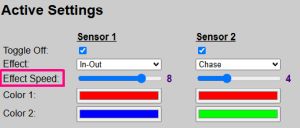
Now the inclination that changing the slider value simply translates to a corresponding fixed delay value. But this breaks down with different effects and how they are rendered. Instead, the “delay” is based calculating a delay value that uses the speed setting and the effect method, along with the total number of LEDs. This method assure that if a speed value of “5” is used, every effect completes its rendering in approximately the same time.
🤦 More Techno-Babble Follows
The following provides details on why the speed calculations are performed as they are. If just using the system, it is not important to understand this information. However, if you are considering creating your own effects or adjusting the default speed scale in the application, this is important to understand
📐 Non-Linear Time Scaling in Spatial Animations
In elementary LED strip programming, animation speed is typically controlled by assigning a fixed millisecond value to a standard delay loop (e.g., delay(50)). While this approach works perfectly for a fixed-length bench test, it completely breaks down in a modular firmware architecture where the animation style can be swapped on the fly and the physical length of the LED strip varies from project to project.
The Structural Problem: Step Mismatches
Because different visual effects rely on entirely different looping mechanics, their execution steps are inherently mismatched:
- Spatial Effects (e.g Chase Effect) iterate through every physical pixel sequentially (N loops).
- Symmetric Effects (e.g.In-Out Effect) split from the center, meaning they only execute half as many total iterations ($\frac{N}{2}$ loops).
- Block Effects (e.g. Segments Effect) slice the staircase into a fixed layout of 5 structural zones, meaning they always execute exactly 5 loop steps regardless of the size of the strip.
- Perceptual Effects (e.g. Fade Effect) iterate cleanly through 8-bit pulse-width modulation brightness configurations rather than physical space bounds.
If a standard frame delay of 30 ms is applied globally to a 100-LED strip:
- The standard chase animation takes exactly 3.0 seconds to run.
- The center-split animation takes only 1.5 seconds to run.
- The segment animation takes a mere 0.15 seconds, flashing instantly before a human eye can process the transitions.
The Solution: Time-Inversion Normalization
To deliver a premium, uniform aesthetic across the entire framework portfolio, the core firmware flips this math upside down. Instead of defining step intervals and letting the total runtime be an accidental byproduct, the system calculates the target total runtime first, and then dynamically divides that window by the geometric constraints of the active animation loop
1. Calculating Total Target Duration
The firmware maps the user-assigned speed slider (ranging from 1 to 10) to a distinct target time scale spanning from 1.5 seconds (Fastest) to 5.0 seconds (Slowest). This linear relationship is calculated using the following display equation:
\[T_{\text{target}} = 5388 - (388 \times S)\]where:
- $T_{\text{target}}$ is the absolute execution budget for the entire animation in milliseconds.
- $S$ is the active speed slider value retrieved from the system configuration file (1 to 10).
2. Deriving the Local Step Delay
Once the macro runtime budget is established, the local animation function samples its own loop block structure to determine exactly how long each micro-step must sleep before calling FastLED.show(): \(\text{delayTime} = \frac{T_{\text{target}}}{\text{Total Loop Steps}}\)
Architectural Step Mappings
By applying this calculation dynamically, step intervals adapt on the fly to fit both the selected effect and the physical length of the installation:
| Effect Mode | Looping Mechanic | Total Step Factor | Step Delay Formula |
|---|---|---|---|
| Chase | Sequential pixel propagation | $\text{numLEDs}$ | $\text{delayTime} = \frac{T_{\text{target}}}{\text{numLEDs}}$ |
| In-Out | Centered bi-directional split | $\frac{\text{numLEDs}}{2}$ | $\text{delayTime} = \frac{T_{\text{target}}}{\left(\frac{\text{numLEDs}}{2}\right)}$ |
| Segments | Fixed 5-block illumination | 5 | $\text{delayTime} = \frac{T_{\text{target}}}{5}$ |
| Fade* | Linear 8-bit brightness scaling | $\text{activeLEDBrightness}$ | $\text{delayTime} = \frac{T_{\text{target}}}{\text{activeLEDBrightness}}$ |
Adjusting the Speed Scale
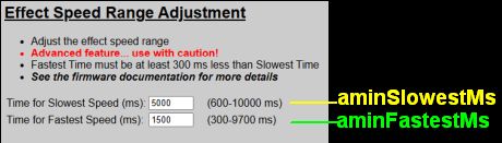
The system is delivered with default values for calculating $T_{\text{target}}$. These are set to 1.5 seconds at the highest speed setting (10) and 5 seconds for the slowest speed setting (1). The example above shows values of 5,388 and 388 for the target time calculations. Where do these come from?
A separate function is used to take the speed scale settings and appropriate calculate the slope and intercept to provide the correct delay values for a given effect.
//----------------------------------
// Calculation for effect step delay
//----------------------------------
uint32_t getTargetDuration(byte speedSetting) {
  int32_t slope = ((int32_t)animFastestMs - (int32_t)animSlowestMs) / 9;  //9 "steps" in the speed range of 1-10
  int32_t intercept = (int32_t)animSlowestMs - slope;

  int32_t calculatedTarget = intercept + (slope * speedSetting);

  // Guard Check: Ensure we never drop below the user's defined fastest target
  if (calculatedTarget < (int32_t)animFastestMs) {
    calculatedTarget = animFastestMs;
  }

  // Hardware transmission data floor limit (numLEDs * numLEDs * 0.03ms)
  uint32_t hardwareFloor = (numLEDs * numLEDs * 3) / 100;

  return max((uint32_t)calculatedTarget, hardwareFloor);
}
Within each effect, we can then get the total time from the function and use that for the local $T_{\text{target}}$ and apply it using the formula for the effect type:
void effectChase(CRGB ledColor, byte speed) {
  uint32_t totalTime = getTargetDuration(speed);
  uint32_t delayTime = totalTime / numLEDs;
  for (int i=0; i < (numLEDs); i++) {
    LEDs[i] = ledColor;
    FastLED.show();
    delay(delayTime);
  }
}
Relative Speeds
But there is still an issue here. While all effects will complete in the same time based on speed setting, the relative speed setting observed will vary based on the total length and number of LEDs in the strip(s).
Assume an LED strip consisting of 100 LEDs. With a speed setting of 10 and an effect of “Chase”, the led strip would be fully illuminated in 1.5 seconds (based on the default animFastestMs of 1500 ms). But if we use those same exact settings on LED strips of different lengths:
-
50 LEDs: The strip will still complete the effect in 1.5 seconds, but since there are only half has many LEDs, the ‘relative’ speed will be 1/2 that of the 100 LED strip.
-
200 LEDs: Again, since the effect will render in the same 1.5 seconds, the ‘relative’ speed will be twice as fast since double the number of LEDs have to be lit in the same time period.
This is where the Speed Range Adjust setting can come into play. Using this same example, if I want the same “relative” speed as a 100 LED strip on the other two lengths, I’d simply half or double the speed range settings.
100 LED Strip

50 LED Strip
Since the relative speed appears half as fast as the 100 LED strip (since only 1/2 the LEDs have to be lit in the same time period), we need to ‘speed up’ the delay by halving the speed range.

200 LED Strip
In this case, the relative speed for the appears twice as fast as the 100 LED strip (since only 1/2 the LEDs have to be lit in the same time period), we need to ‘slow down’ the delay by doubling the speed range.

Now, the 50 LED strip will only take 1/2 the time and the 100 LED strip double the time to render as the 100 LED strip, but the ‘relative’ speed on all three versions will be close to the same.
Note: This isn’t exact as the speed calculation isn’t linear, but it is close enough! So if you have a very long LED strip and even the slowest speed seems to fast or a short strip where the fastest speed is too slow (or vice versa), you can adjust the Speed Range to best match your installation.
Limitations and Caveats on the Speed Range
Due to how the eye perceives the effects and since rendering the effects is a “blocking” function, there are some hard limitations to the Speed Range values.
- Slowest Speed: Must be between 600 - 10000 ms
- Fastest Speed: Must be between 300 - 9700 ms
- Minimum Gap: The fastest time must be at least 300 ms less than the slowest time
Why are these limitations necessary?
⏱️ Understanding Animation Speed Limits
1 - The Fastest Speed Limit
The system implements a maximum speed limit of 300ms (500ms or greater recommended). This cap exists because of how addressable LEDs (like the WS2812B) physically communicate.
-
The 30-Microsecond Law: Addressable LEDs do not update instantly. The single-wire data protocol requires exactly 30 microseconds to transmit the color data for a single pixel down the line.
-
The Animation Multiplier: In spatial animations (like the “Chase” effect), the controller doesn’t just update the strip once. It must refresh the entire physical strip at every single step of the animation.
-
The Physical Wall: If you have a short strip of 30 LEDs, data travels fast enough to allow hyper-fast speeds. However, if you are running a massive strip of 300+ LEDs, the microcontroller physically cannot push the bits down the copper wire fast enough to finish a chase in under a couple of seconds—even if the software delay is set to zero.
The upper limit prevents the software from requesting an impossible speed that the physical LED chips cannot support.
2 - The Slowest Speed Limit
The system implements a maximum slow-speed limit of 10,000ms (10 seconds) to complete a full animation. This cap is critical for maintaining system stability and responsiveness.
-
Blocking Code Loops:
While the controller is executing a fluid animation loop, it is actively running micro-delays to pace the visual effect. These are “blocking” cycles, meaning the processor is entirely focused on timing the LEDs. -
Network Deafness:
While stuck in a long blocking loop, the ESP32 cannot instantly respond to background tasks. If an animation is allowed to stretch out to 20 or 30 seconds, the controller will temporarily ignore MQTT background pings, ignore web browser requests, and—most importantly—miss incoming wireless trigger packets from a secondary sensor at the opposite end of the stairs or hallway.
Capping the slowest speed ensures that animations remain beautifully gradual without causing the controller to drop offline or miss the user’s next movement. Long blocking functions can also cause watchdog events on the ESP32, which could result in sudden reboots.
Fading Effects
If you look WAY back towards the top of this section under the section on Architechural Effect Mappings, you’ll notice that the Fade effect has an asterisk beside the name and that the Step Factor uses the LED brightness setting instead of the number of LEDs or a fixed number. The speed setting value (1 - 10) is still used to control how fast a fade occurs, but the calculations have to be handled differently.
👁️ Perceptual Brightness & The Fade Curve
When creating a dimming or fading effect for LEDs, standard linear math (like counting from 0 to 255) results in a surprisingly clunky animation. To create a fade that looks perfectly fluid, the firmware must translate “machine logic” into a format that matches human optical biology.
1 - Human Vision vs. Machine Brightness
The human eye does not perceive light linearly. Human eyes are incredibly sensitive to tiny changes in low-light conditions, but highly insensitive to the exact same changes in broad daylight (a rule known as the Weber-Fechner Law).
-
The Linear Problem: If you increase an LED’s power by a steady amount (e.g., 1, 2, 3, 4…), your eyes see a sudden, aggressive flash right at the start. By the time the LED reaches 70% power, your eyes are saturated; the remaining climb to 100% looks like it completely stalls out.
-
The Solution: To make an animation look linear to a human, the actual power output must follow an exponential curve—starting with microscopic steps at the bottom and making massive leaps at the top end.
2 - Why the Firmware Uses FastLED’s dim8_video()
To generate this exponential curve without slowing down the controller with heavy mathematical processing, the firmware utilizes FastLED’s native dim8_video() algorithm.
-
Flicker-Free Shadow Starts: Standard mathematical curves often suffer from integer rounding errors, rounding low inputs (like 1, 2, or 3) down to absolute 0. This causes the strip to stay pitch black and then suddenly “pop” awake.
-
The Video Guard: The
dim8_video()function includes a hardware protective clause: any input greater than 0 is guaranteed to output at least the absolute minimum hardware voltage. This ensures the LED strip flows smoothly right out of total darkness without a jagged edge.
3 - Percent-Based Master Scaling
A major pitfall in LED fading architecture occurs when trying to fade toward a custom master brightness setting (for example, a dim nighttime setting of 64 out of 255).
-
The Final Jump Trap: If a fade loop simply counts up to the master brightness setting, the gamma curve compresses the values so heavily that the animation maxes out way below the actual target. When the animation ends, the strip instantly snaps to the true master setting, causing a jarring, bright flash.
-
The Percentage Fix: The firmware fixes this by running every fade through a standardized 0% to 100% timeline. At each step, the code passes the progress through the human perception curve first, and then scales that curved value down to fit the user’s web-configured master brightness.
By separating the fade progress from the final brightness value, the animation retains its ultra-smooth resolution whether the stairs are fading up to a soft, dim nightlight accent or a blazing 100% full illumination.
🌄 A Few Additional Notes About the Built-In Fade Effect
The provided Fad effect still uses the effect speed setting to control how fast an LED fades from “off” to the current LED brightness setting. But note the following:
At low settings and due to the exponential curve (small adjustments at initial brightnes), there may appear to be a delay between a sensor trigger and visible light on the LEDs. This isn’t a bug, but due to the small brightness range, initial loops may not set the brightness level actually high enough to visualize on the LEDs.
The Fade Effect therefore works best with higher LED brightness settings.
Armed with the above knowledge, you can now create your own custom effects for the LED controller!