Partitions and Flashing
![[Partitions image]](images/advancedpartitions_01.jpg)
This information is critical if you are manually flashing source code via the Arduino IDE or a third-party utility. If you are simply using the web-based “Firmware Upgrade” feature with the provided .bin files, the system handles the memory offsets for you. However, for the developers out there, here is how we manage the “real estate” inside the ESP32.
The “Sketch Too Large” Problem
Due to the complexity of the firmware and the inclusion of the web application strings, the binary is too large to fit into a standard ESP32 partition. To solve this, we “borrow” space normally reserved for the SPIFFS (the local file system). Since our configuration files are tiny JSON strings, we can safely shrink the SPIFFS area and give that extra room to the primary sketch.
🖥️ Full vs. Update .bin Files
This partitioning is why the releases contain both a _Full.bin and a _Update.bin file. When flashing the _Full.bin file, the new partitions are created as part of the installation. This will cause the destruction and loss of any pre-existing data, which is why upgrading an existing system with the _Full.bin file causes loss of the existing configuration. Alternatively, attempting to install the _Update.bin file on a new board only updates the sketch area, but since the correct partitions do not exist, it gets written to the wrong area and generally results in a boot loop.
Arduino IDE Configuration
When using the Arduino IDE to compile and flash the source code, you must change the partition scheme from the “Default” setting. Failure to do this will result in a compilation error stating that the firmware is too large for the available space.
In the Tools menu, ensure your settings match the following:
- Board:
ESP32 Dev Module - Partition Scheme:
Minimal SPIFFS (1.9MB APP with OTA/190KB SPIFFS)
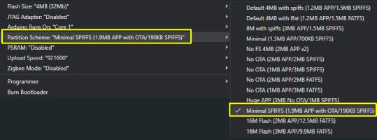
Manual Partition Table
If you are using a different IDE or a specialized flashing utility (like the Espressif Download Tool), you will need the specific memory offsets and sizes. If these aren’t set correctly, the ESP32 will likely fall into a “boot loop” as it tries to find its code in the wrong neighborhood.
| Partition Name | Type | Subtype | Offset | Size |
|---|---|---|---|---|
| nvs | data | nvs | 0x9000 | 0x5000 (20KB) |
| otadata | data | ota | 0xe000 | 0x2000 (8KB) |
| app0 | app | ota_0 | 0x10000 | 0x1E0000 (1.875MB) |
| app1 | app | ota_1 | 0x1F0000 | 0x1E0000 (1.875MB) |
| spiffs | data | spiffs | 0x3D0000 | 0x30000 (~190KB) |
💡 Fun Fact
By using this “Minimal SPIFFS” layout, we still have two identicalappslots (OTA0 and OTA1). This is what allows a controller to perform a “Safe Update”—it downloads the new firmware into the empty slot and only switches over if the download is successful. It’s like wearing a belt and suspenders at the same time!
Manually Flashing Firmware Updates
While you should normally apply firmware updates using the native web application, if you run into issues or have another need to manually update the firmware without completely overriding your current settings, you can do so with a utlitily like ESPConnect. But you’ll need to determine which app slot is active and get the offset for that slot.
When you perform an OTA update, and as described above, the new firmware gets uploaded to the ‘non-active’ slot. If successful, the otadata partion, which tracks the active app slot, switches over to use the newly updated version. However, when manually updating via USB, the otadata partition isn’t updated. If the update is installed to the wrong slot, it will never actually execute and you’ll remain on the previous version. But this is easy to resolve.
Once you’ve connected your ESP32 controller via USB, select the ‘Apps’ menu from the left hand side of ESPConnect.
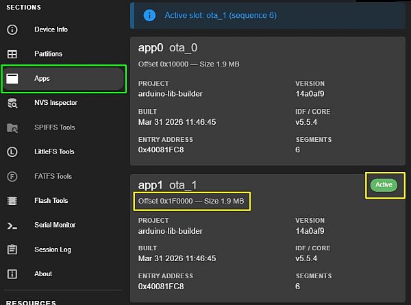
This page indicates which slot is curernt “active”. This is the slot where you need to upload the new sketch. Note the offset for the active slot as we’ll need it for the next step. In this case, since app1 is active, we’ll need to use offset 0x1F0000. If app0 had been active, then the offset would be 0x100000.
Once you have the active app slot and offset, open up the Flash Tools from the left menu.
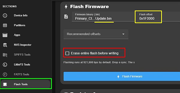
- If applying a sketch update, assure you’ve selected the appropriate
_Update.binfile. - Set the correct offset, depending on which App slot is active.
- Verify the ‘Erase entire flash’ is UNCHECKED or your current configuraiton will be overwritten and the controller may not boot without a complete full install and onboarding.
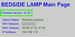
Once the flash completes, you can disconnect the ESP32 and install back in the project. You can always verify whether an update was successful by checking the version number at the top of the web application.
⚠️ REMINDER: Firmware Files are NOT Interchangeable
Double-check your file! Sending a Display update to the Primary controller (or vice versa) is a quick way turn your project into a dark brick! You will likely need to reflash a full install, onboard and configure again to recover.